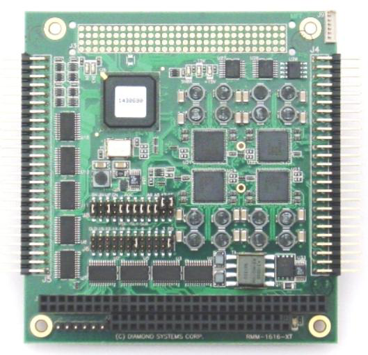
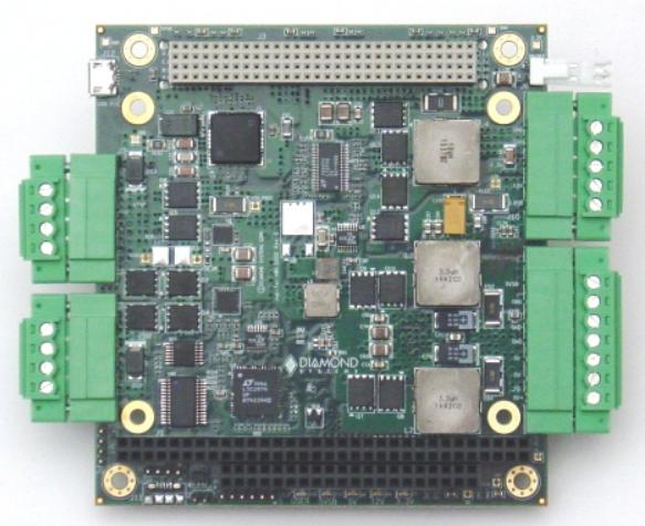
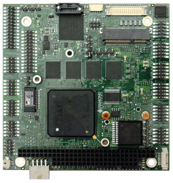
Analog I/O Module
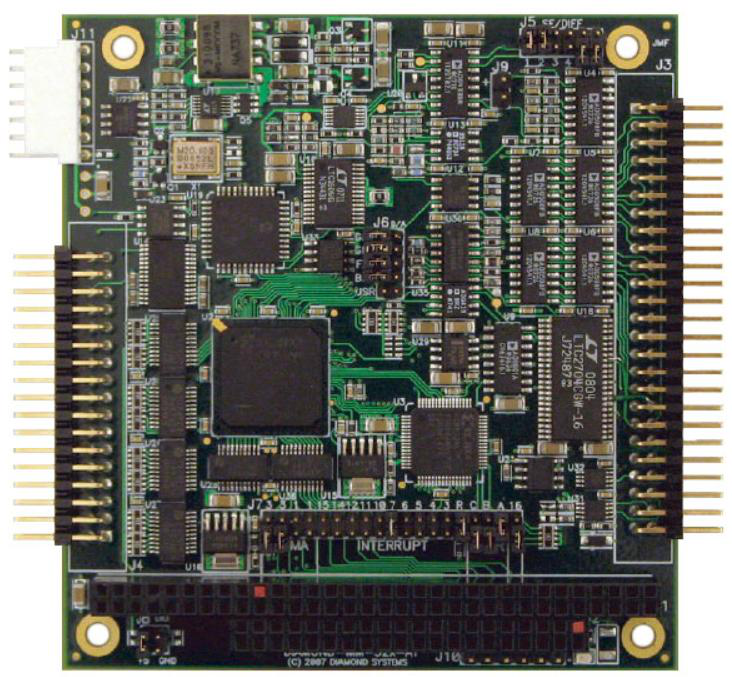
Diamond-MM-32DX-AT
DMM-32DX-AT is Diamond Systems’ most advanced embedded A/D board. It includes a comprehensive suite of analog and digital features to fit a wide variety of embedded application
Specifications
| Analog Inputs | |
|---|---|
| Number of inputs | 32 single-ended, 16 differential, or 16 SE + 8 DI; user selectable |
| A/D resolution | 16 bits (1/65,536 of full scale) |
| Bipolar ranges | ±10V, ±5V, ±2.5V, ±1.25V, ±0.625V |
| Unipolar ranges | 0-10V, 0-5V, 0-2.5V, 0-1.25V, 0-.625V, |
| Input bias current | 100pA max |
| Overvoltage protection | ±35V on any analog input without damage |
| Input Impedance | 10^13 ohms |
| Nonlinearity | ±3LSB, no missing codes |
| Conversion rate | 250,000 samples/sec.max |
| On-board FIFO | 1024 16-bit samples |
| Calibration | Automatic;values stored in EEPROM |
| Analog Outputs | |
| Number of outputs | 4 |
| D/A resolution | 16-bits (1/65536 of full scale) standard, 12-bits (1/4096 of full scale) optional |
| Output ranges | ±5, ±10, 0-5, 0-10, ±2, 5V, programmable in I/O, 53mV steps |
| Output current | ±5mA max per channel |
| Settling time | 6µS max to 0.01% |
| Relative accuracy | ±1 LSB |
| Nonlinearity | ±1 LSB, monotonic |
| Reset | Reset to zero-scale or mid-scale (jumper selectable) |
| Calibration | Automatic; values stored in EEPROM |
| Waveform Buffer | 1,024 samples, cyclical |
| Digital I/O | |
| Main I/O | 24 programmable I/O |
| Input current | ±1µA max |
| Output current | |
| Logic 0 | 64mA max per line |
| Logic 1 | -15mA max per line |
| Auxilary I/O | 4 inputs, 4 outputs, optional use as trigger/control lines |
| Counter/Timers | |
| A/D Pacer clock | 32-bit down counter (2 82C54 counters cascaded) |
| Clock source | 10MHz on-board clock or external signal |
| General purpose | 16-bit down counter (1 82C54 counter) |
| General | |
| Power supply | +5VD±10%@410mA typ |
| Operating temperature | -40°C to +85°C |
| Weight | 3.4oz/96g |
| MTBF | 972,275 hours at +20°C |
| RoHS | Compliant |
DIAMOND-MM-16R-AT
The DMM-16R-AT features top performance and flexibility for a mid-range price. It has 16 single-ended / 8 differential analog voltage inputs with both unipolar and bipolar input ranges, programmable gain, and a maximum sampling rate of 100KHz. The 4 D/A channels and 16 digital I/O lines provide additional real-world control and monitoring capability.
Specifications
| Analog Inputs | |
|---|---|
| Number of inputs | 8 differential or 16 single-ended (user selectable) |
| A/D resolution | 16 bits (1/65,536 of full scale) |
| Bipolar ranges | ±10V, ±5V, ±2.5V, ±1.25V, ±0.625V |
| Unipolar ranges | 0-10V, 0-5V, 0-2.5V, 0-1.25V |
| Input bias current | current 3nA max |
| Overvoltage protection | ±35V on any analog input without damage |
| Input Impedance | 10^13 ohms |
| Nonlinearity | ±3LSB, no missing codes |
| Conversion rate | 100,000 samples/sec. max with interrupts |
| Conversion trigger | Software trigger, internal pacer clock, or external TTL signal |
| Input FIFO | 512 samples,256-sample interupt threshold |
| A/D interrupt | End of A/D conversion |
| End of A/D scan | |
| FIFO half-full | |
| Calibration | A/D and D/A circuits calibrated under software control using on-board precision references and EEPROM storage |
| Analog Outputs | |
| Number of outputs | 4 |
| D/A resolution | 12 bits (1/4096 of full scale) |
| Output ranges | Fixed: ±5, 0-5V |
| Programmable: Anywhere between 0V and 10V in 1mV increments | |
| Reset: All channels reset to mid-scale (0V for bipolar ranges) | |
| Output current | ±5mA max per channel |
| Settling time | 6µS max to 0.01% |
| Relative accuracy | ±1 LSB |
| Nonlinearity | ±1 LSB, monotonic |
| Digital I/O | |
| Number of lines | 16, organized as 2 8-bit ports |
| Logic Levels | 3.3V / 5V jumper selectable |
| Termination | 10K ohm pull-up / pull-down resistors, jumper selectable |
| Input voltage | Vlogic = 5V |
| Logic 0 | 1.65V max |
| Logic 1 | 3.35V min |
| Output voltage | Vlogic = 5V |
| Logic 0 | 0.44V max, Iout = 24mA |
| Logic 1 | 3.76V min, Iout = -24mA |
| Input voltage | Vlogic = 3.3V |
| Logic 0 | 0.80V max |
| Logic 1 | 2.00V min |
| Output voltage | Vlogic = 3.3V |
| Logic 0 | 0.44V max, Iout = 24mA |
| Logic 1 | 2.25V min, Iout = -24mA |
| Counter/Timers | |
| A/D Timer clock | 32-bit down counter |
| General purpose | 16-bit down counter |
| Clock source | 10MHz on-board clock or external signal |
| General | |
| Bus Interface | ISA (5V) bus |
| Power supply | +5V ±5% @ 390mA typical |
| Operating temperature | -40°C to +85°C tested and guaranteed |
| Weight | 64g / 2.25oz |
| RoHS | Compliant |
DIAMOND-MM-16RP-AT
The DMM-16R-AT features top performance and flexibility for a mid-range price. It has 16 single-ended / 8 differential analog voltage inputs with both unipolar and bipolar input ranges, programmable gain, and a maximum sampling rate of 100KHz. The 4 D/A channels and 16 digital I/O lines provide additional real-world control and monitoring capability.

Specifications
| Analog Inputs | |
|---|---|
| Number of outputs | 8 differential or 16 single-ended (user selectable) |
| A/D resolution | 16 bits (1/65,536 of full scale) |
| Bipolar ranges | ±10V, ±5V, ±2.5V, ±1.25V, ±0.625V |
| Unipolar ranges | 0-10V, 0-5V, 0-2.5V, 0-1.25V |
| Input bias current | 3nA max |
| Overvoltage protection | ±35V on any analog input without damage |
| Input Impedance | 10^13 ohms |
| Nonlinearity | ±3LSB, no missing codes |
| Conversion rate | 100,000 samples/sec. max with interrupts |
| Conversion trigger | Software trigger, internal pacer clock, or external TTL signal |
| Input FIFO | 512 samples, 256-sample interrupt threshold |
| A/D interrupt | End of A/D conversion |
| End of A/D scan | |
| FIFO half-full | |
| Calibration | A/D and D/A circuits calibrated under software control using on-board precision references and EEPROM storage |
| Analog Outputs | |
| Number of outputs | 4 |
| D/A resolution | 12 bits (1/4096 of full scale) |
| Output ranges | Fixed: ±5, 0-5V |
| Programmable: Anywhere between 0V and 10V in 1mV increments | |
| Reset: All channels reset to mid-scale (0V for bipolar ranges) | |
| Output current | ±5mA max per channel |
| Settling time | 6µS max to 0.01% |
| Relative accuracy | ±1 LSB |
| Nonlinearity ±1 LSB, monotonic |
|
| Digital I/O | |
| Number of lines | 16, organized as 2 8-bit ports |
| Logic Levels | 3.3V / 5V jumper selectable |
| Termination | 10K ohm pull-up / pull-down resistors, jumper selectable |
| Input voltage | Vlogic = 5V |
| Logic 0 | 1.65V max |
| Logic 1 | 3.35V min |
| Output voltage | Vlogic = 5V |
| Logic 0 | 0.44V max, Iout = 24mA |
| Logic 1 | 3.76V min, Iout = -24mA |
| Input voltage | Vlogic = 3.3V |
| Logic 0 | 0.80V max |
| Logic 1 | 2.00V min |
| Output voltage | Vlogic = 3.3V |
| Logic 0 | 0.44V max, Iout = 24mA |
| Logic 1 | 2.25V min, Iout = -24mA |
| Counter/Timers | |
| A/D Timer clock | 32-bit down counter |
| General purpose | 16-bit down counter |
| Clock source | 10MHz on-board clock or external signal |
| General | |
| Bus Interface | Dual PCI (3.3V) and ISA (5V) buses supported; Autoselects for PCI bus; manual override option |
| Power supply | +5V ±5% @ 375mA typical |
| ±15V output | current ±10mA max with DACs unloaded |
| Operating temperature | -40°C to +85°C tested and guaranteed |
| Weight | 80g / 2.84oz |
| RoHS | Compliant |
Diamond-MM-AT
The new Diamond-MM-AT analog I/O module offers autocalibration, programmable gain, A/D FIFO, and extended temperature operation to mid-range 12-bit analog I/O users. All these features are added on top of our existing Diamond-MM architecture at the same price as the original board, to bring you an unbeatable combination of features at this price level.
Specifications
Input Impedance
| Analog Inputs | |
|---|---|
| Number of outputs | 8 differential or 16 single-ended (user selectable) |
| A/D resolution | 12 bits (1/4096 of full scale) |
| Bipolar ranges | ±10V, ±5V, ±2.5V, ±1.25V, ±0.625V |
| Unipolar ranges | 0-10V, 0-5V, 0-2.5V, 0-1.25V |
| Input bias current | 3nA max |
| Max. input voltage | ±10V for linear operation |
| Overvoltage protection | ±35V on any analog input |
| 10^13 ohms | |
| Conversion rate | 100,000 samples per second with interrupts |
| Input FIFO | 512 samples, interrupt on half-full |
| Analog Outputs | |
| Number of outputs | 2 |
| D/A resolution | 12 bits (1/4096 of full scale) |
| Output ranges | Fixed: ±5V, 0-5V |
| Programmable: anywhere between 0V and 10V in 1mV increments | |
| Output current | ±5mA max per channel |
| Settling time | 4µS max to ±2/2 LSB |
| Relative accuracy | ±1 LSB |
| Nonlinearity | ±1 LSB, monotonic |
| Reset | All channels reset to OV |
| Digital I/O | |
| Number of inputs | 8, HCT/TTL compatible |
| Input voltage | |
| Logic 0: | 0.0V min, 0.8V max |
| Logic 1: | 2.0V min, 5.0V max |
| Input current | ±1µA max |
| Number of outputs | 8, HCT/TTL compatible |
| Output voltage | |
| Logic 0: | 0.0V min, 0.33V max |
| Logic 1: | 3.8V min, 5.0 max |
| Output current | |
| Logic 0: | 64mA max per line |
| Logic 1: | -15mA max per line |
| Counter/Timers | |
| A/D Pacer clock | 32-bit down counter (2 82C54 counters cascaded) |
| Clock source | 10MHz on-board source or external signal |
| General purpose | 16-bit down counter (1 82C54 counter) |
| Interrupt trigger | End of A/D conversion or scan |
| General | |
| Calibration | A/D and D/A circuits calibrated under software control |
| Power supply | +5VD±10%@350mA typical |
| ±15V output current | ±10mA max with DACs unloaded |
| Operating temperature | -40°C to +85°C Extended |
| Weight | 3.3oz/93 |
| RoHS | Compliant |
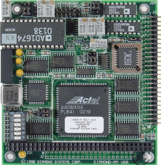
Diamond-MM
Diamond-MM has all the primary features you expect in a high-performance analog I/O board at a reduced price. The analog input circuit uses a 12-bit A/D converte and can be configured for single-ended or differential input wiring, as well as unipolar or bipolar input ranges. It also offers 10 different input ranges, so it can work with a wide variety of input signals. The maximum A/D conversion rate is approximately 2,000-20,000 per second using interrupts (depending on the operating system) or 100,000 per second using DMA.
Specifications
| Analog Inputs | |
|---|---|
| Number of inputs | 8 differential or 16 single-ended (user selectable) |
| A/D resolution | 12 bits (1/4096 of full scale) |
| Bipolar ranges | ±10V, ±5V, ±2.5V, ±1V, ±0.5V, Custom |
| Unipolar ranges | 0-10V, 0-5V, 0-2.5V, 0-1V, 0-.5V, Custom |
| Input bias current | 50nA max |
| Max. input voltage | ±10V for linear operation |
| Overvoltage protection | ±35V on any analog input |
| Input Impedance | 10^13 ohms |
| Conversion trigger | software trigger, internal pacer clock, or external TTL signal |
| Analog Outputs | |
| Number of outputs | 2 |
| D/A resolution | 12 bits (1/4096 of full scale) |
| Output ranges | 0-5V, adjustable, or external reference input |
| Output current | ±8mA max per channel |
| Settling time | 4µS max to ±2/2 LSB |
| Relative accuracy | ±1 LSB |
| Nonlinearity | ±1 LSB, monotonic |
| Reset | All channels reset to OV |
| Digital I/O | |
| Number of inputs | 8, HCT/TTL compatible |
| Input voltage | |
| Logic 0: | 0.0V min, 0.85 max |
| Logic 1: | 2.0V min, 5.0V max |
| Input current | ±1µA max |
| Number of outputs | 8, HCT/TTL compatible |
| Output voltage | |
| Logic 0: | 0.0V min, 0.33 max |
| Logic 1: | 3.8V min, 5.0 max |
| Output current | ±4mA max per line |
| Counter/Timers | |
| A/D Pacer clock | 32-bit down counter (2 82C54 counters cascaded) |
| Clock source | 10MHz on-board source or external signal |
| General purpose | 16-bit down counter (1 82C54 counter) |
| Interrupt/DMA trigger | End of A/D conversion |
| General | |
| Power supply | +5VD±10%@165mA typical |
| ±15V output current | ±10mA max with DACs unloaded |
| Operating temperature | 0°C to +70°C Standard, -40°C to +85°C Extended |
| Weight | 3.3oz/93g |
| MTBF | DMM-XT 372,809 hours |
| RoHS | Compliant |
Ruby-MM-1616A
The Ruby-MM-1616 PC/104 module provides up to 16 channels of 16-bit resolution analog voltage or current output. The output range can be individually selected for 0-5V, 0-10V, ±5V, ±10V, 0-20mA, 4-20mA, or 0-24mA. All outputs are updated simultaneously, either with a software command or in response to an external signal. A waveform generator is available on up to 16 channels with simultaneous updating of all channels.
Specifications
| Analog Outputs | |
|---|---|
| Number of outputs | 4, 8, or 16 |
| Resolution | 16-bits |
| Output ranges | 0-5V, 0-10V unipolar, ±5V, ±10V bipolar |
| 0-20mA, 4-20mA, 0-24mA | |
| Settline time | 10us maximum to ±.003% |
| Linearity error | ±2 LSB maximum |
| Differential nonlinearity | ±2 LSB maximum |
| Monotonicity | 15 bits minimum |
| Maximum output current | ±5mA/2KO minimum load |
| Reset | All DACs reset to 0V |
| Calibration | Digital with internal scale and offset registers for each channel |
| Waveform generator | Up to 16 channels |
| Digital I/O | |
| Number of lines | 40 byte-wide, 8 bit-wide, programmable direction |
| CMOS/TTL compatible (82C55) | |
| Input voltage | Logic 0: -0.5V min, 0.8V max |
| Logic 1: 2.0V min, 5.5V max | |
| Output voltage | ±Logic 0: 0.0V min, 0.4V max |
| Logic 1: 3.0V min, 4.6V max | |
| Output current | ±2.5mA maximum per line |
| Pull-up resistor | 10KO on each I/O lines |
| External trigger | TTL/CMOS compatible, 10KO pull-up resistor, active high edge |
| Reset | All digital I/O lines are set to input and all data registers are set to 0 |
| Counter/timers | 2 32-bit programmable; 40MHz clock |
| Pulse width modulators | 4 24-bit |
| General | |
| Input Power | +5VDC ±10% |
| Operating temperature | -40°C to +85°C Extended |
| Dimensions | 90mm x 96mm (3.55" x 3.775") |
| Form Factor | PC/104 compliant |
| Weight | 3.0oz (85g) |
| MTBF | 100,000 hours |
| RoHS | Compliant |
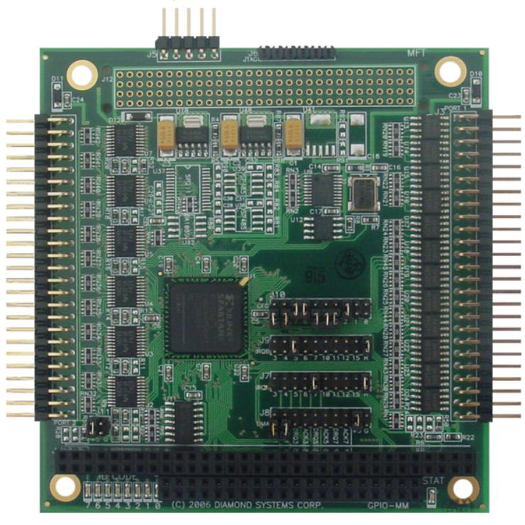
Digital I/O Module
GPIO-MM
GPIO-MM is a PC/104 digital I/O module based on an FPGA, allowing multiple feature sets to be implemented on the same hardware platform. The FPGA is a Xilinx Spartan 2 RAM-based device with 200K gates (XC2S200). An on-board configuraton flash memory device stores the FPGA code for automatic loading on power-up, and new code can be downloaded using a JTAG cable connected to a PC. Several standard off the shelf personalities are available, and custom ones can be developed either by users with Xilinx tools or by Diamond as a customization service.
Specifications
| Base FPGA | Xilinx Spartan II, 200,000 gates, 40K RAM bits |
| Input clock | 40MHz |
| FPGA code storage | Flash memory, field upgradeable via JTAG |
| ID indicator | 8-bit LED display indicates FPGA code personality |
| No. of I/O pins | 100 pins (48 buffered) |
| Programmable Digital I/O | 48 using 8255 cores |
| Fixed Direction I/O | 8 fixed inputs and 8 fixed outputs |
| Counter/timers | 10 16-bit, using 9513 cores |
| Max counting freq | 40MHz |
| Counter modes | Counter, rate/square-wave generator, programmable one-shot, hardware/software triggered strobe |
| Output current, buffered I/O | Logic 0: 64mA max per line |
| Ouptut current,fixed I/O and fixed counter/timers | ±24mA max |
| Dimensions | 3.55" x 3.775", PC/104 form factor |
| PC/104 bus | 16-bit stackthrough ISA bus |
| Power supply | +5VDC ±5% |
| Operating temperature | -40°C to +85°C standard, all versions |
| RoHS | Compliant |
GPIO-MM-12
GPIO-MM-12 is part of a family of reconfigurable digital I/O and counter / timer modules with various port and pin configurations. Each board uses identical hardware with a 200K gate Xilinx Spartan II RAM-based FPGA. The varying configurations are based on different FPGA code. The FPGA code is stored in a flash memory on the board, enabling GPIO-MM-12 to be reprogrammed in the field with different designs, including custom designs.
Specifications
| Base FPGA | Xilinx Spartan II, 200,000 gates, 40K RAM bits |
| Input clock | 40MHz |
| FPGA code storage | Flash memory, field upgradeable via JTAG |
| No. of I/O pins | 100 pins (48 buffered) |
| Programmable Digital I/O | 48 using 8255 cores |
| Fixed Direction I/O | 8 fixed inputs and 8 fixed outputs |
| Counter/timers | 10 16-bit, using 9513 cores |
| Max counting freq | 40MHz |
| Counter modes | Counter, rate/square-wave generator, pulse-width modulator, programmable one-shot, hardware/software triggered strobe |
| Output current, buffered I/O | Logic 0: 64mA max per line |
| Ouptut current, fixed I/O and fixed counter/timers | ±24mA max |
| Dimensions | 3.55" x 3.775", PC/104 form factor |
| PC/104 bus | 16-bit stackthrough ISA bus |
| Power supply | +5VDC ±5% |
| Operating temperature | -40°C to +85°C standard, all versions |
| RoHS | Compliant |
GPIO-MM-21
GPIO-MM-21 is part of a family of reconfigurable digital I/O and counter / timer modules with various port and pin configurations. Each board uses identical hardware with a 200K gate Xilinx Spartan II RAM-based FPGA. The varying configurations are based on different FPGA code. The FPGA code is stored in a flash memory on the board, enabling GPIO-MM-21 to be reprogrammed in the field with different designs, including custom designs.
Specifications
| Base FPGA | Xilinx Spartan II, 200,000 gates, 40K RAM bits |
| Input clock | 40MHz |
| FPGA code storage | Flash memory, field upgradeable via JTAG |
| ID indicator | 8-bit LED display indicates FPGA code personality |
| No. of I/O pins | 100 pins (48 buffered) |
| Programmable Digital I/O | 96 using 8255 cores |
| Output current, buffered I/O | Logic 0: 64mA max per line |
| Dimensions | 3.55" x 3.775", PC/104 form factor |
| PC/104 bus | 16-bit stackthrough ISA bus |
| Power supply | +5VDC ±5% |
| Operating temperature | -40°C to +85°C standard, all versions |
| RoHS | Compliant |
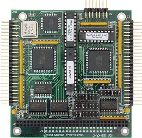
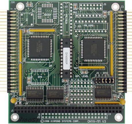
Onyx-MM
Extensive software control of features is the highlight of this digital I/O module featuring 48 digital I/O lines, 3 16-bit counter/timers, and 3 independent PC bus interrupt inputs.
The 48 digital I/O lines on Onyx-MM are based on 2 82C55 ICs. They can be programmed for input or output in groups of 8 lines. Direct as well as strobed (latched) I/O modes are supported, and all I/O lines are connected to 10K Ohm pull-up resistors.
Specifications
| Counter/Timers | |
|---|---|
| Chip | 82C54-2 |
| Counter/timers | 3, 16 bits wide |
| Maximum input freq. | 10MHz |
| On-board osc. | 4MHz ±.01% |
| Signal type | TTL |
| Input voltage | |
| Low: | -0.5V min, 0.8V max |
| High: | 2.0V min, 5.5V max |
| Input current | -200µA max (low), 2µA max (high) |
| Output voltage | |
| Low: | 0.0V min, 0.4V max |
| High: | 3.0V min, Vcc -0.4V max |
| Output current | ±2.5mA max, each line |
| Pullup resistors | 10KO all input lines |
| Digital I/O | |
| Chip | 82C55A (qty. 2) |
| Number of I/O lines | 48, TTL/CMOS Compatible |
| Direction | All lines programmable for input in groups of 4 and 8 |
| Output current | ±2.5mA max, each line |
| Pullup resistors | 10KO all input lines |
| Interrupts | |
| Number of interrupts | 3 |
| Pull-down resistor | 1KO resistor selectable via jumper on each interrupt |
| Interrupt level | 2 - 7 |
| Interrupt sources | Counter/timer outputs, Interrupt input, or DIO lines CO (programmable) |
| General | |
| Power supply | +5V ±10% @ 120mA typical all outputs open |
| Temperature | -40° to +85°C extended |
| PC/104 Bus | 8 bits |
| Weight | 2.8 oz/79g |
| RoHS | Compliant |
Onyx-MM-DIO
This module is the same as our Onyx-MM digital & counter/timer module but without the counter/timer and interrupt circuitry. This board still has the quality and attention to detail of our other modules, such as: 10K Ohm pull-up resistors on all I/O lines; all ports reset to 0 on power-up or system reset; connector pinouts compatible with our other digital I/O boards; and free software.
The 48 digital I/O lines on Onyx-MM-DIO are based on 2 82C55 ICs. They can be programmed for input or output in groups of 8 lines. Direct as well as strobed (latched) I/O modes are supported, and all I/O lines are connected to 10K Ohm pull-up resistors.
Specifications
| Digital I/O | |
|---|---|
| Chip | 82C55A (qty. 2) |
| Number of I/O lines | 48 |
| Direction | Programmable in groups of 4 or 8 |
| Input voltage | |
| Low: | -0.5V min, 0.8V max |
| High: | 2.0V min, 5.5V max |
| Output voltage | |
| Low: | 0.0V min, 0.4V max |
| High: | 3.0V min, Vcc -0.4V max |
| Output current | ±2.5mA max, each line |
| Pullup resistors | 10KO all input lines |
| General | |
| Power supply | +5V ±10% @ 120mA typical all outputs open |
| Temperature | -40°C to +85°C |
| PC/104 Bus | 8 bits |
| Weight | 2.3 oz/65g |
| MTBF | OMM-DIO-XT 1,714,901 hours |
| RoHS | Compliant |
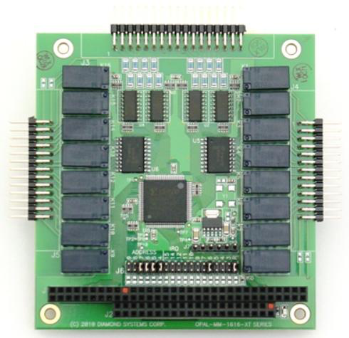
Opal-MM-1616 Opto In + Relay Out Module
pal-MM-1616 is a PC/104 format digital I/O module designed for industrial applications requiring isolation between the computer and the external signals it is monitoring and controlling.
Specifications
| Optoisolated Inputs | |
|---|---|
| Number of inputs | 16 unidirectional optoisolated inputs |
| Input capacity | 30VDC with current limiting resistors |
| Input impedance | 8k ohms |
| Logic levels | Logic 0: 0 - 1.5VDC |
| Logic 1: 3 - 30VDC | |
| Programmability | Programmable edge detection with interrupts |
| Relay Outputs | |
| Number of outputs | 16 relay outputs |
| Relay contacts | SPDT (Form C) contacts |
| Break before make | |
| Current capacity | 2A |
| Switching capacity | 30VDC at 2A |
| 125VAC at 0.1A resistive | |
| Maximum switching capacity | 30W (DC) |
| Contact resistance | 50mohm max |
| Actuation time | Operate: 5ms maximum |
| Release: 5ms maximum | |
| Relay lifetime | 10,000,000 operations |
| General | |
| I/O header | Optoisolated inputs: 1 34-pin (2 x 17) header on .1" connector |
| Relay outputs: 2 26-pin (2 x 13) headers on .1" connecters | |
| Mating Cables: | C-34-18 for optoisolated inputs |
| C-26-18 for relay outputs (quantity 2) | |
| Isolation (all I/O) | 500VDC or AC, input to board or board to output |
| Channel to channel isolation | |
| Power supply | +5VDC ±10% |
| Current consumption | 70mA typical, all relays off; additional 28mA per activated relay |
| Bus interface | PC/104 (ISA) bus |
| Form factor | PC/104 (3.55" x 3.775") |
| Operating temperature | -40°C to +85°C (-40°F to +185°F) |
| Weight | 3.4oz (96g) |
| Universal Driver support | |
| RoHS | Compliant |
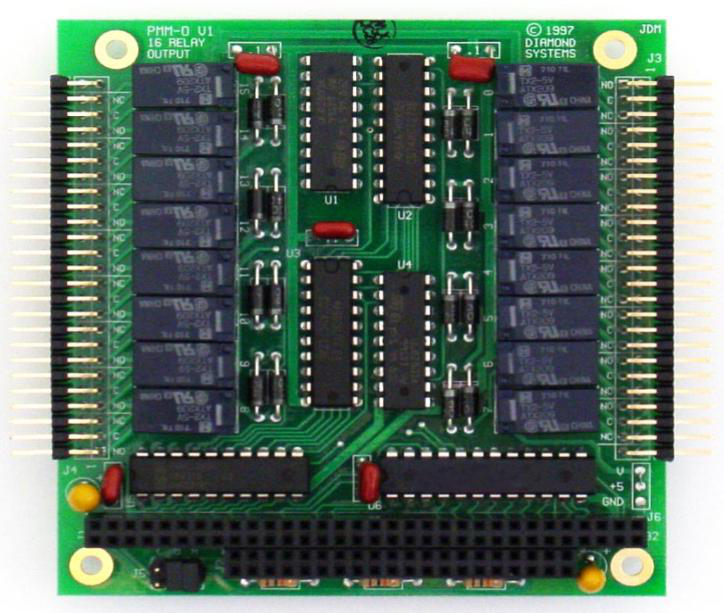
Pearl-MM Relay Output Module
Pearl-MM is a PC/104 format industrial control module with 16 relays. The relays have PDT (form C) configuration. Each relay has 3 contacts: Common, Normally Open, and Normally Closed. For safety and reliability, all relays are in their power-off state (Common connected to Normally Closed) at power-up or system reset. The relays can switch both AC and DC voltages. They feature long life (100,000,000 operations), quick actuation time (4ms max operate and release), and isolation (500V AC or DC).
Specifications
| Relays | |
|---|---|
| No. of Outputs | 16 |
| Relay type | SPDT (Form C) |
| Max voltage/current DC: | 0VDC/2A 60W (DC), 60VA (AC) |
| AC: 125VAC/0.5A resistive | |
| Max switching capacity | 220VDC, 250VAC |
| Max operating voltage | 10mA@10mVDC |
| Contact resistance | 100mO max |
| Relay lifetime | 100,000,000 operations |
| Actuation time | 4ms max operate or release |
| General | |
| I/O connections | 50-position (2x20) .025” square pin header on .1” centers |
| Isolation (all I/O) | 500VDC or AC, channel-to-channel and channel-to-board |
| Power supply | +5VDC ±10% |
| Operating temperature | -40°C to +85°C |
| Operating humidity | 5% to 95% non-condensing |
| Weight | 3.4oz / 96g |
| MTBF | 118,227 hours |
| RoHS | Compliant |
IR104-PBF Opto In & Relay Out Module
IR104-PBF is a high-density PC/104 format digital I/O module designed for industrial applications requiring isolation between the computer and the external signals it is monitoring and controlling. This module features 20 optoisolated digital inputs and 20 relay outputs. Each input can accept both AC and DC voltages as low as 3V and as high as 24V.
Specifications
| Inputs | 20 Optoisolated inputs |
| Input voltage | 3-24V AD or AC |
| Input impedance | 2.8KO |
| Outputs | 20 SPST relays |
| Max voltage | 150VDC, 250 VAC |
| Max current | 5A AC or DC (30VDC max) |
| Max power | 150W, 1250VA |
| Contact resistance | 30mO initially |
| UL rating | 5A/30VDC or 250VAC 1/10HP 120VAC |
| Lifetime | 20,000,000 cycles mechanical 100,000 cycles @ full power |
| Actuation time | 6ms operate, 3ms release |
| I/O connectors | |
|---|---|
| Inputs: | 2x20 pin header, .1" spacing |
| Outputs: | Dual 1x20 detachable screw terminals |
| Power | 5V @ 110mA typ (all relays off) |
| Operating Temp | -25°C to +70°C |
| Size | 3.550" x 3.775" |
| 0.492" max component height | |
| Weight | 3.2 oz/90g |
| MTBF | 57,450 hours |
| RoHS | Compliant |
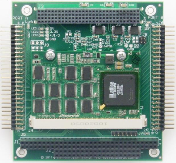
P104-GPIO96
P104-GPIO96 is a programmable PCI-104 DIO module using a high-capacity (700K gate equivalent) PCI Express FPGA for maximum density and flexibility. The base hardware configuration features 96 digital I/O lines grouped into 12 8-bit ports. All ports have I/O buffers to protect the FPGA and feature 5V logic drive levels. The ports are organized into a combination of byte-wide, nibble-wide, and bit-wide direction control for maximum flexibility and application compatibility.
Specifications
| Base FPGA | LatticeECP3, 700K gate equivalents |
| Input clock | 50MHz |
| FPGA code storage | Flash memory, field upgradeable via JTAG |
| Total I/O lines | 96 |
| Primary I/O | 48 lines with 3 8-bit and 2 4-bit; configurable pull-up/down resistors |
| Secondary I/O | 48 lines with 6 8-bit buffers; configurable pull-up/down resistors |
| Counter/timers | 8 32-bit up/down counters (alternate mode) |
| Max counting frequency | (coming soon) |
| Counter modes | Counter, rate/square-wave generator, pulse-width modulator, programmable one-shot, hardware/software triggered strobe |
| Output current | Ports A, B & D: 24mA per pin max; 200mA per port max |
| Port C low: 24mA per pin max | |
| Port C high: -24mA per pin max | |
| Ports E & F: 32mA per pin max | |
| Input current | +/-340uA max |
| Form Factor | PC/104-Plus |
| Expansion | PC/104-Plus (ISA + PCI) stackable expansion |
| Dimensions | 3.55 x 3.775 in. (90 x 96 mm) |
| Power supply | 3.3VDC ±5% |
| Operating temperature | -40°C to +85°C standard |
| Weight | 3.4oz (96g) |
| RoHS | Compliant |
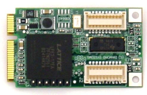
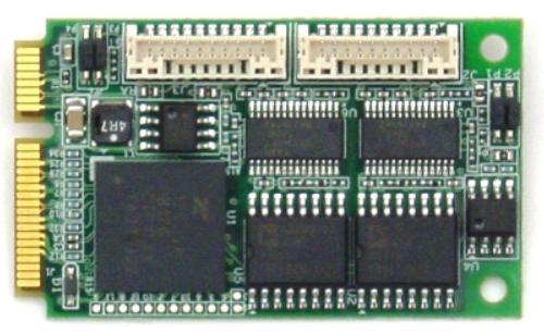
DS-MPE-GPIO
The DS-MPE-GPIO is a rugged, low cost 36-channel digital I/O PCIe MiniCard module that is ideal for digital I/O expansion in embedded and OEM applications.
An FPGA provides 36 buffered digital I/O lines that can be configured to operate in simple I/O mode in the form of 8-bit and 4-bit ports, or in counter/timer and pulse width modulator modes. Two ports are fixed digital I/O ports with programmable direction in 8-bit groups. One port can operate as either a 4-bit DIO or 4 counter/timers with 1 input and 1 output per counter. One port can operate as either 8 DIO or up to 8 pulse width modulators.
Specifications
| Number of DIO | 36 |
| Pull-up / Pull-down | Software configurable |
| Transceivers | 3245 with high current output |
| Power-up / Reset | DIO in input mode |
| Pulse Width Modulators | Up to 4 24-bit circuits configurable |
| 0-100% duty cycle | |
| On/off control | |
| Programmable polarity | |
| Counter / Timers | 4 32-bit circuits configurable Programmable |
| Input power | +3.3VDC +/-5% |
| Power consumption | 100mA @ 3.3V |
| Software drivers | Windows 7, XP, CE |
| Linux 2.6.16, 2.6.27, 2.6.31, 2.6.32 | |
| Universal Driver | Support for all functions |
| Form Factor | PCIe MiniCard full size |
| Dimensions | 50.95 x 30mm (2 x 1.18") |
| Operating temperature | -40ºC to +85ºC |
| Operating humidity | 5% to 95% noncondensing |
| MTBF | tbd |
| Weight | 8.5g (0.3oz) |
| RoHS | Compliant |
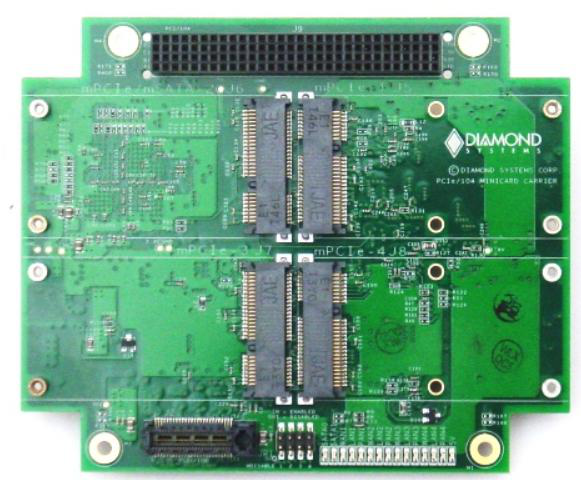
PCIe MiniCard Carrier
The PCIe MiniCard carrier offers four PCIe MiniCard sockets on a compact PCI/104 Express form factor board. All four sockets have PCIe x 1 and USB interfaces and support full size and half size PCIe MiniCard modules.
The module provides full support to all sockets while consuming only a single lane of host SBC resources. SIM card support is provided for two sockets.
Specifications
| Number of PCIe MiniCard sockets | 4 |
| Card Size | Full and half size cards supported |
| SIM support | 2 sockets support SIM cards |
| Interfaces | PCIe x1 and USB |
| Host interface | PCI-104 pass through |
| LEDs | LEDs provided for all 4 sockets |
| Form FactorDimensions | PCI/104-Express form factor with wings: 4.5" x 3.775" (114mm x 96mm) |
| Power supply | +5VDC ±5% |
| Operating temperature | -40°C to +85°C (-40°F to +185°F) |
| Operating humidity | 5% to 95% non-condensing |
| Shock | MIL-STD-202G compatible |
| Vibration | MIL-STD202G compatible |
| MTBF | tbd hours at 20°C |
| Weight | 2.5oz (71g) |
| RoHS | Compliant |
Serial I/O Module
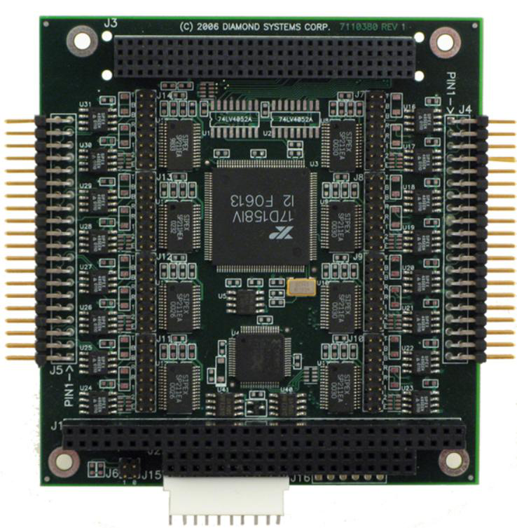
Emerald-MM-8PL-XT
Emerald-MM-8PL offers 8 multi-protocol serial ports on a single PC/104 module with complete software configurability via the operating system. Each port can be individually selected for RS-232, RS-422, or RS-485 under software control. Both local-echo and non-local-echo modes are supported for RS-485. I/O addresses and interrupt levels are also programmable, with interrupt sharing available for any number of ports. Each port may further be enabled or disabled in software. All configuration data is stored in an on-board EEPROM that is loaded automatically on power-up.
Specifications
| Serial Ports | |
|---|---|
| Number of serial ports | 8 |
| Protocols | RS-232, RS-422, RS-485 (local and no echo) |
| Configuration | All features software configurable |
| Maximum baud rate | 460.8kbps |
| Communications parameters | 5, 6, 7, or 8 data bits; Even, odd, or no parity |
| Short circuit protection | Continuous, all outputs |
| RS-232 mode | |
| Input Impedance | 3KO min |
| Input voltage swing | ±30V maximum |
| Output voltage swing | ±5V min, ±7V typical |
| RS-422/RS-485 modes: | |
| Differential input threshold | -0.2V min, +0.2V max |
| Input impedance | 12KO minimum |
| Input current | +1.0mA max (Vin = 12V) |
| -0.8mA max (Vin = -7V) | |
| Differential output voltage | 2.0V min (RL=50O) |
| High/low states differentia output voltage symmetry | 0.2V max |
| Digital I/O | |
| Number of I/O lines | 8 in, 8 out |
| Input voltage | Low: -0.3V min, 0.8V max |
| Output voltage | Low: 0.0V min, 0.4V max (IOL = 6mA max) |
| General | |
| I/O header | 2 40-position (2x10) .025" square pin header on .1" centers; |
| Headers mate with standard ribbon cable (IDC) connectors | |
| Dimensions | 3.55" x 3.775" |
| Power supply | +5VDC ±10% |
| Current consumption | 160mA typical, all outputs unloaded |
| Operating temperature | -40°C to +85°C standard, all versions |
| MTBF | EMM-8P-XT: 490,502 hours |
| RoHS | Compliant |
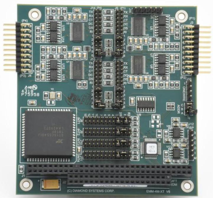
Emerald-MM-4M 4-Port
Our Emerald-MM PC/104 module gives you 4 serial ports operating at speeds up to 115kbps.
In RS-232 mode, the full complement of standard PC serial port signals (8 signals + ground) are provided for each port and are grouped onto two 20-pin headers (2 ports per header). In RS-422 mode, Signals RX+, RX-, TX+, and TX- are provided, along with ground. In RS-485 mode, signals TX+/RX+ and TX-/RX- are provided, along with ground.
Specifications
| Serial Ports | |
|---|---|
| Number of serial ports | 4 |
| Protocol | RS-232, RS-422, RS-485 (jumper selected) |
| Maximum baud rate | 115kbps standard version |
| 460.8kbps available (EMM-HS-XT) | |
| Communications parameters | 5, 6, 7, or 8 data bits |
| Even, odd, or no parity | |
| Short circuit protection | All outputs protected against continuous short circuit |
| RS-232 mode: | |
| Input impedance | 3KO minimum |
| Input voltage swing | ±30V maximum |
| Output voltage swing | ±5V min, ±7V typical |
| RS-422, RS-485 modes: | |
| Differential | -0.2V min, +0.2V max input threshold |
| Input impedance | 12KO minimum |
| Input current | +1.0µA max (VIN = 12V) |
| -0.8µA max (VIN = -7V) | |
| Differential output voltage | 2.0V min (RL=50O) |
| High/low states differential output voltage symmetry | 0.2V maximum |
| General | |
| I/O header | 2 20-position (2x10) .025" square pin header on .1" center; |
| Headers mate with standard ribbon cable (IDC) connectors | |
| Dimensions | 3.55" x 3.775" |
| Power supply | +5VDC ±10% |
| Current consumption | 80mA typical, all outputs unloaded |
| Operating temperature | -40°C to +85°C Extended |
| Operating humidity | 5% to 95% noncondensing |
| PC/104 bus | 8-bit and 16-bit bus headers are installed |
| Weight | 2.6oz/74g |
| MTBF | EMM-4M-XT 555,428 hours |
| RoHS | Compliant |
Emerald-MM-Opto 4-Port Opto
Emerald-MM-Opto provides an integrated, rugged, and reliable solution for PC/104-expandable embedded systems requiring serial communications in demanding applications. It offers 2 or 4 optically isolated serial ports with RS-232, RS-422, and RS-485 protocols, as well as 24 digital I/O lines, all on a single board.
Specifications
| Serial Ports | 2 or 4, RS-232/422/485 |
| Data Rates | RS-232, 230.4kbps max |
| RS-422/485: 460.8kbps max | |
| Signals | RS-232: RXD, TXD, RTS, CTS |
| RS-422/485: RXD, TXD | |
| Addresses | 8 preconfigured standard I/O address options; custom addresses available |
| Interrupts | IRQ levels 2, 3, 4, 5, 6, 7, 10, 12, 15; |
| Interrupt sharing supported | |
| Isolation | 1000V AC or DC, port to port or port to system |
| Termination | 150? with 1K? pull-up/pull-down |
| UART | 16C2850 with 128-byte FIFO and auto-flow control |
| Digital I/O | 24 programmable direction using 82C55 |
| DIO termination | 10K? pull-up |
| Connectors | Individual 10-pin connector for each serial port; 26-pin connector for digital I/O |
| Bus PC/104 | 16-bit bus (8-bit data) |
| Power | +5VDC @ 300mA typical, all outputs open |
| Operating Temperature | -40ºC to +85ºC |
| Dimensions | 3.550"W x 3.775"H |
| RoHS | Compliant |
Emerald-MM-8PLUS 8-Port
Emerald-MM-8Plus is a high performance multi-protocol serial communications board offering eight ports on a single PC/104-Plus module. Supporting baud rates up to 921.6K bps in RS-232 mode or 1.8432Mbps in RS422 or RS485 mode, each port can be individually selected for RS-232, RS-422, RS-485 or TTL level operation. Both local-echo and non-local-echo modes are supported for RS-485. Protocol selection is achieved via a jumper block for each of the eight ports. Line termination for RS-422/485 modes is also jumper-selectable.
Specifications
| Serial Ports | |
|---|---|
| Number of serial ports | 8 |
| Protocols | RS-232, RS-422, RS-485 (local and no echo) |
| Protocol Configuration | Jumpers |
| Software Configuration | Plug and Play |
| Maximum baud rate | 1.8432Mbps |
| Communications parameters | 5, 6, 7, or 8 data bits; Even, odd, or no parity |
| Short circuit protection | Continuous, all outputs |
| RS-232 mode | |
| Input Impedance | 3KO min |
| Input voltage swing | ±30V maximum |
| Output voltage swing | ±5V min, ±7V typical |
| RS-422/RS-485 modes: | |
| Differential input threshold | -0.2V min, +0.2V max |
| Input impedance | 12KO minimum |
| Input current | +1.0mA max (Vin = 12V) |
| -0.8mA max (Vin = -7V) | |
| Differential output voltage | 2.0V min (RL=50O) |
| High/low states differentia output voltage symmetry | 0.2V max |
| Digital I/O | |
| Number of I/O lines | 8 individually programmable |
| Input voltage | Logic 0: -0.3V min, 0.8V max |
| Logic 1: 2.0V min, 5.3V max | |
| Output voltage | 0: 6mA max |
| 1: -4mA max | |
| General | |
| I/O header | 2 40-position (2x20) .025" square pin header on .1" centers; |
| Headers mate with standard ribbon cable (IDC) connectors | |
| Dimensions | 3.55" x 3.775" |
| Power supply | +5VDC ±10% |
| Current consumption | 160mA typical, all outputs unloaded |
| Operating temperature | -40°C to +85°C standard, all versions |
| Weight | 3.1oz (87.9g) |
| RoHS | Compliant |
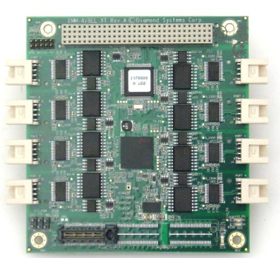
Emerald-MM-8EL 4- or 8-Port
The Emerald-MM-8EL-XT is a family of high performance PCIe/104 "OneBank" serial I/O modules offering 4 or 8 multiprotocol serial ports with software-controlled configuration and optional opto-isolation.
Specifications
| Serial Ports | |
|---|---|
| Number of serial ports | 4 or 8 |
| Protocols | RS-232, RS-422, RS-485 configured with software, no jumpers |
| Maximum baud rate | RS-232 mode: 1Mbps |
| RS-422/485 mode: 10Mbps | |
| UART | 16550 compatible octal UART with 256-byte TX/RX FIFOs |
| Transceivers | SP330 multiprotocol transceivers, one per port |
| Communications parameters | 5, 6, 7, or 8 data bits; Even, odd, or no parity |
| Termination | Software programmable RS-422/485 termination |
| Isolation | Independent 2500VRMS isolation port-by-port |
| ESD protection | +/-15KV on each port |
| Short circuit protection | Continuous, all outputs |
| RS-232 mode | |
| Input Impedance | 3KO min |
| Input voltage swing | ±30V maximum |
| Output voltage swing | ±5V min, ±7V typical |
| RS-422/485 modes | |
| Differential input threshold | -0.2V min, +0.2V max |
| Input impedance | 12KO minimum |
| Input current | +1.0mA max (Vin = 12V) |
| -0.8mA max (Vin = -7V) | |
| Differential output voltage | 2.0V min (RL=50O) |
| High/low states differential output voltage symmetry | 0.2V max |
| Digital / Analog I/O | |
| Number of lines | 8 individually programmable lines: |
| 8 as digital input or output | |
| 7 as 12-bit analog input | |
| Analog input ranges | 0-2.048V or 0-3.3V |
| General | |
| Host interface | PCIex1 using PCIe/104 OneBank connector |
| Inrush current | Staggered turn-on of isolated devices for reduced inrush current at power on |
| On-board microcontroller | On-board PIC microcontroller with flash to manage and store configurations |
| Connectors | Latching connectors on all ports for increased ruggedness |
| Dimensions | 3.55" x 3.775" (90mm x 96mm) |
| Conforms to PCIe/104 OneBank form factor supporting Type 1 and Type 2 | |
| Power supply | +5VDC ±5% |
| Current consumption | 160mA typical, all outputs unloaded |
| Software drivers | Windows Embedded Standard 7, XP, 2000 and Vista |
| Linux 2.6.16, 2.6.31 and 2.6.32 | |
| Operating temperature | -40°C to +85°C (-40°F to +185°F) |
| Operating humidity | 5% to 95% non-condensing |
| Shock | MIL-STD-202G compatible |
| Vibration | MIL-STD202G compatible |
| MTBF | 579,352 hours at 20°C |
| Weight | 2.5oz (71g) |
| RoHS | Compliant |
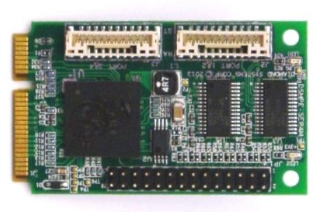
DS-MPE-SER4M
The DS-MPE-SER4M is a rugged, low cost 4-port high speed PCIe MiniCard module that is ideal for serial I/O expansion in embedded and OEM applications. Extended temperature capability (-40°C to +85°C) enables the board to operate in environments with extreme temperature swings, such as vehicles or outdoor installations. In addition, the board may be custom-configured with 0-ohm resistors in place of jumper blocks for increased ruggedness in high-vibration environments.
Specifications
| Number of serial ports | 4 |
| Protocols | RS-232/422/485 on each port jumper or software configured |
| Maximum baud rate | RS-232: 1Mbps |
| RS-422/485: 10Mbps | |
| UARTs | 16550 compatible |
| FIFO | 256-byte TX/RX |
| ESD protection | +/-15KV |
| Input power | +3.3VDC +/-5% |
| Power consumption | 0.462W @ 3.3V |
| Software drivers | Windows XP |
| Linux 2.6.16, 2.6.27, 2.6.31, 2.6.32 | |
| Form Factor | PCIe MiniCard full size |
| Dimensions | 50.95 x 30mm (2 x 1.18") |
| Operating temperature | -40ºC to +85ºC |
| Operating humidity | 5% to 95% noncondensing |
| MTBF | tbd |
| Weight | 8.5g (0.3oz) |
| RoHS | Compliant |
DS-MPE-SER4OPT Opto
The DS-MPE-SER4OPT is a rugged, low cost 4-port opto-isolated PCIe MiniCard serial module that is ideal for serial I/O expansion in embedded and OEM applications.
Extended temperature capability (-40°C to +85°C) enables the board to operate in environments with extreme temperature swings, such as vehicles or outdoor installations. In addition, the board may be custom-configured with 0-ohm resistors in place of jumper blocks for increased ruggedness in high-vibration environments.
Specifications
| Number of serial ports | 4 |
| Protocols | RS-232/485 on each port, configured in pairs |
| Maximum baud rate | RS-232: 1Mbps |
| RS-485: 10Mbps | |
| Termination | RS-485 jumper selectable |
| UARTs | Quad XR17V354 with PCIe interface |
| FIFO | 256-byte TX/RX |
| Transceiver | SP336 multi-mode |
| Isolation | +/-500V input/output |
| Input power | +3.3VDC +/-5% |
| Power consumption | 0.462W @ 3.3V |
| Software drivers | Windows 7, XP, Vista, 2000 |
| Linux 2.6.16, 2.6.27, 2.6.31, 2.6.32 | |
| Form Factor | PCIe MiniCard full size |
| Dimensions | 50.95 x 30mm (2 x 1.18") |
| Operating temperature | -40ºC to +85ºC |
| Operating humidity | 5% to 95% noncondensing |
| MTBF | tbd |
| Weight | 8.5g (0.3oz) |
| RoHS | Compliant |

Recent Comments