Top 10 Reasons to Use sTCAE suite of tools for Model Based Design of Embedded Control Systems:
1. Rapid Development of Control Systems
Keywords: # Auto-Code Generation, Digital Control Systems, Digital Motor Controls, Digital Power, HIL, Electric Drives, Robotics, Electric Vehicles, Hybrid Vehicles, Digital Battery Management Systems, State Charts, Texas Instruments C2000, Delfino, Piccolo, Texas Instruments MSP430, Instaspin, Motorware.
solidThinking Embed is an award winning graphical block diagram language for modeling and simulating complex dynamic systems. The core product of the suite, sT Embed, is a highly efficient and comprehensive model-based embedded systems development tool which allows development of quick prototypes of any dynamic system by going from Control Diagrams to auto-generated C-code ready to be ported onto target hardware. Embed also provides a much sought after State Charts to Auto-code generation feature. The well proven diagram to code technology of Embed Tool helps shorten your design & development time drastically while increasing product consistency and quality. Embed automatically converts the Control Diagrams and Model into highly-efficient and compact ANSI Ccode(pure fixed point code option available) for discrete, continuous and hybrid systems. Embed Tool provides designers with the option of natively scheduling multi-rate or multi-threaded code and download it onto target Embedded hardware along with necessary peripheral drivers all developed using model based design approach. This shortens development cycle drastically.
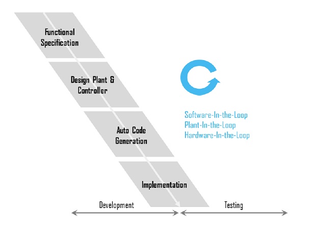
MBD development consists of 3 main phases – simulation phase, also known as Software in the Loop or SIL; the microprocessor in the loop phase, also known as Processor in the Loop or PIL; and the hardware in the loop phase, also known as Hardware in the Loop or HIL
solidThinking Embed provides a complete toolchain for the development of embedded control systems covering Software-in-the-Loop, Processor-in-the-Loop as well as Hardware-in-the-Loop simulations.
You can make changes to a control diagram, and compile and download it to the target MCU in seconds. Then, while the system is operating, you can interactively update the control parameters. Using powerful data logging, buffering, and digital scoping blocks, you can gain insight into the control algorithms deployed on the target MCU in real time.
7. Improve System Level Performance
I Simulate and imporve the dynamic performance of smart, multi-deciplinary systems. Integrate multi-domain, multi-department systems in an open environment
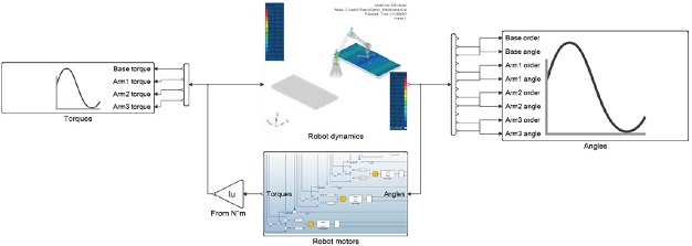
Simulate and improve the dynamic behavior of any multi-disciplinary system. A system simulation environment makes it easy to model, simulate and validate smart systems where users can incorporate functions of sensing, actuation and control coming from diverse components such as Electrical, Mechanical, Hydraulics and Controls.
In this example, the motors that help actuate the robot was modeled in Activate. The multibody dynamics mechanism was modeled in MotionSolve. Activate helps you perform integration and synthesis by allowing you incorporate multi-disciplinary components and simulate a combined system behavior
8. Efficiently Design For Robustness
I Perform what-if-analyses at the system-level to quickly test several designs of your smart system. Perform design studies and optimization with parametric models to best meet requirements and determine the most influential design parameters
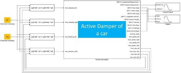
Adopting Model Based Development establishes a common framework for communication throughout the design process. Model based development using Activate provides an efficient approach for establishing a common framework for communication throughout the design process. Perform what-if analyses at the system level to quickly test several designs and investigate the interactions of all components in a system.
The example that you see on your slide is that of a vehicle dynamics simulation. By modifying the damping factor on the suspension, you monitor how the lateral stability of the car changes. The Activate hybrid simulator runs models very quickly. This allows you to perform several what-if studies on your concept and thereby influence the robustness of your design.
10. Interactive & Robust Host-Target Communication & Debugging :
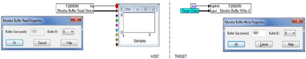
During the PIL phase, the controller algorithm is converted to code using the sTE automatic code generation feature and executed on the Target microprocessor. The plant model, including the sensor and actuator models, remain on the Host. Sensor and actuator signals are passed between the Host and Target using the JTAG based interactive data exchange. The solidThinking Embed application provides a built-in USB based JTAG communication link (HotLink) that allows (1) the Target to be interactively controlled from the Host and (2) real time data collection from the Target with presentation or storage on the Host. Since the JTAG interface has bandwidth limitations, sTE provides the ability to adjust the Target update time such that the sensor/actuator data transfer between the plant and controller remains synchronized. The solidThinking Embed communication layer, HotLink, communicates using JTAG to support both normal and high speed data collection. The normal mode is used to send commands from the Host to the Target and collect data from the Target to the Host. The signal transfer rate is limited to approximately 200 words/second. During the PIL and HIL phases, data must be acquired at a much faster rate, typically one prefers to record data at the frequency the control algorithm is running at which could be 10kHz or greater. A special block set is provided that executes over the JTAG interface specifically for this purpose. The Monitor Buffer provides a mechanism for a debug model to buffer a large volume of data acquired on the Target at the Target’s native sample rate, transmit the data periodically over the slower JTAG interface from the Target to the Host, and then make the buffer contents available as a vector of data on the Host application. The monitor buffer shown below uses the buffer mechanism to capture, transmit a buffer of 1001 elements collected at 10,000 Hz from the Target. The Host, running at 100Hz, then plots the sample values much like a triggered oscilloscope trace
In addition to the plant model, the Host model is enhanced with sliders and other signal producers allowing parameters to be interactively adjusted while the controller is running. Furthermore, the Host model may be modified to capture high speed data collection from the Target using the monitor buffer feature described later in this paper. Since the modeling uncertainty of the Target model used in the SIL phase is removed in the PIL phase, the level of confidence in meeting the design requirements is improved compared with the SIL phase. The solidThinking Embed application utilizes a JTAG interface to communicate data between the Host and the Target