PC CAN Interfaces
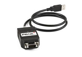
The CAN-FD adapter PCAN-USB FD allows connection to CAN-FD and CAN networks via the USB port of a computer. A galvanic isolation up to a maximum of 500 volts decouples the PC from the CAN bus. Thanks to the simple application and its compact plastic housing, the adapter is ideally suited for mobile use. The new standard CAN FD (CAN with Flexible Data Rate) is characterized above all by higher bandwidths during data transmission. The maximum 64 data bytes of a CAN-FD frame (instead of 8) can be transmitted at bit rates of up to 12 Mbps. CAN FD is down-compliant to the CAN standard 2.0 A / B, so that CAN-FD nodes can be used in existing CAN networks. However, the CAN-FD extensions are not applicable.
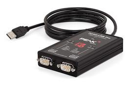
The PCAN-USB Pro FD adapter allows connection to CAN-FD and LIN networks via the USB port of a computer. Two fieldbuses can be connected at the same time, with up to four (2 x CAN FD, 2 x LIN) with corresponding adapter cables. Each CAN-FD channel is insulated separately from USB and LIN with a maximum of 500 volts. Thanks to its robust aluminium housing, the PCAN-USB Pro FD adapter is ideally suited for mobile applications. The new standard CAN FD (CAN with Flexible Data Rate) is characterized above all by higher bandwidths during data transmission. The maximum 64 data bytes of a CAN-FD frame (instead of 8) can be transmitted at bit rates of up to 12 Mbps. CAN FD is downwards compatible with the CAN standard 2.0 A / B, so that CAN-FD nodes can be used in existing CAN networks. However, the CAN-FD extensions are not applicable.
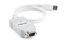
The PCAN-USB adapter allows uncomplicated connection to CAN networks. Due to its compact plastic housing, it is ideally suited for mobile applications. With the opto-isolated version, a galvanic isolation of up to 500 volts is ensured between the PC and the CAN side. The supplied CAN monitor PCAN-View for Windows ® and the programming interface PCAN-Basic complete the package.
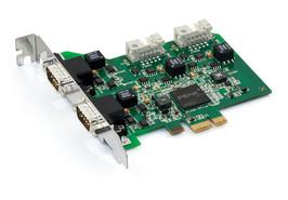
The PCAN-PCI Express card allows the integration of a PC with PCI Express slots in CAN networks. There is a galvanic isolation between the computer side and the CAN side up to a maximum of 500 volts. The card is available as a single, two or four channel version. The supplied CAN monitor PCAN-View for Windows® as well as the programming interface PCAN-Basic round off the package.
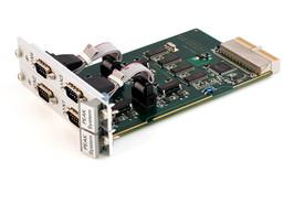
The PCAN-cPCI card allows the integration of an industrial computer system with CompactPCI into CAN networks. There is a galvanic isolation between the computer side and the CAN side up to a maximum of 500 volts. The card is available as a two- or four-channel version. The supplied CAN monitor PCAN-View for Windows ® and the programming interface PCAN-Basic complete the package.
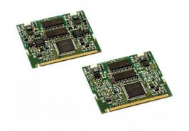
The PCAN miniPCI card allows the integration of embedded PCs and laptops with mini PCI slots in CAN networks. The card is available as a single or dual channel version. In the opto-decoupled versions, a galvanic isolation of up to 300 volts is provided between the PC and the CAN side. The supplied CAN monitor PCAN-View for Windows ® and the programming interface PCAN-Basic complete the package.
PC CAN Couplers & Converters
The PCAN-Optoadapter is a universal plug-in adapter for the galvanic decoupling of high-speed CAN bus systems. Due to the integrated logic, decoupling is possible at any point in the CAN network. The PCAN-Optoadapter can be used in CAN-FD buses with data transmission rates of up to 2 Mbit / s and nominal transmission rates of up to 1 Mbit / s.
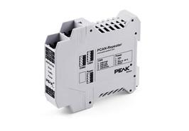
The PCAN repeater DR connects between two high-speed CAN buses with a galvanic isolation up to 5 kV. The two CAN channels as well as the CAN channels and the voltage supply are decoupled from each other. The entire messaging traffic including error frames is relayed between the two channels 1 to 1, if necessary only in one direction. The PCAN repeater DR behaves passively and is transparent from the point of view of the CAN bus. LEDs indicate the current bus status. With the H-rail housing and the support of the extended temperature range, the module is suitable for use in industrial environments. The PCAN repeater DR can be used in CAN-FD buses with data transmission rates of up to 4 Mbit / s and nominal transmission rates of up to 1 Mbit / s.
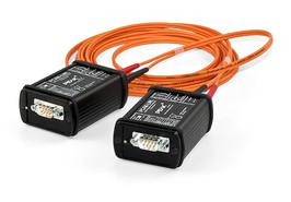
For use in explosion-proof areas or in EMC measurements, a CAN line can be replaced by a fiber optic link at any point through the PCAN fiber optic cable. The implementation is carried out selectively on high-speed CAN or low-speed CAN. The modules are supplied externally. The PCAN optical fiber can be used in CAN-FD buses with data transmission rates of up to 5 Mbps and nominal transmission rates of up to 500 kbit / s.
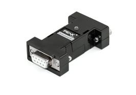
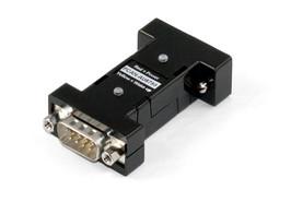
The PCAN-AU5790 bus converter provides a connection between a high-speed CAN bus (ISO 11898-2) and a single-wire CAN bus (SAE J2411). The possible applications of the bus converter include the simple connection of a CAN interface of the PCAN series (eg PCAN-USB) to a single-wire CAN bus.
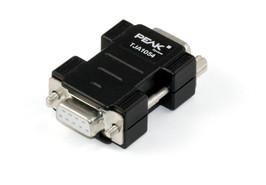
The PCAN-TJA1054 bus converter provides a connection between a high-speed CAN bus (ISO 11898-2) and a low-speed CAN bus (ISO 11898-3). The possible applications of the bus converter include the simple connection of a CAN interface of the PCAN series (eg PCAN-USB) to a low-speed CAN bus.
PC CAN I/O Modules
The PCAN-MicroMod as a plug-in module is a simple way to provide electronic circuits with I / O functionality and CAN connection. The configuration is carried out using a Windows® program, which transmits the configuration data to the module via CAN. Several modules can be configured independently of one another on a CAN bus. With various PCAN-MicroMod basic boards, it is possible to be used in equipment and systems engineering as well as in the automotive industry. An optional evaluation board facilitates the entry and development of own base boards.
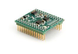
PCAN-Micromod Evaluation Board
The PCAN-MicroMod as a plug-in module is a simple way to provide electronic circuits with I / O functionality and CAN connection. The configuration is carried out using a Windows® program, which transmits the configuration data to the module via CAN. Several modules can be configured independently of one another on a CAN bus. With various PCAN-MicroMod basic boards, it is possible to be used in equipment and systems engineering as well as in the automotive industry. An optional evaluation board facilitates the entry and development of own base boards.
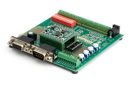
The base boards for the PCAN-MicroMod provide an application-oriented environment. A wide supply voltage range as well as the protective circuitry of the inputs and outputs are typical features of this product group. CANopen ® firmware is available for all PCAN-MicroMod base boards. The Analog 1 & 2 base boards meet general analog requirements.
The base boards for the PCAN-MicroMod provide an application-oriented environment. A wide supply voltage range as well as the protective circuitry of the inputs and outputs are typical features of this product group. CANopen ® firmware is available for all PCAN-MicroMod base boards. The Digital 1 & 2 base boards serve general digital requirements.

The Multiple Input Output Module (MIO) is a universal, modular control unit for industrial and automotive applications. The module has two CAN interfaces as well as several analog and digital inputs and outputs. Incoming signals can be processed via the microcontroller and then output via the CAN interfaces or output channels. The behaviour of the PCAN-MIO module is freely configured for this with a comprehensive Windows ® software. To create such a configuration, the user is provided with a plurality of function blocks and other settings. In addition, the bus structure allows the inputs and outputs to be extended by additional modules. Customer-specific requirements can be implemented here.
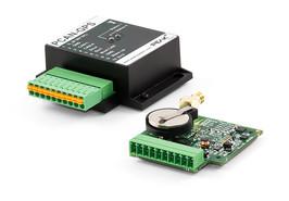
The PCAN-GPS is a freely programmable sensor module for position and position determination. It has a satellite receiver, a magnetic field sensor, an acceleration sensor and a gyroscope. The acquired data can be transferred to a CAN bus and recorded on the internal memory card. Data collected is processed by a microcontroller of the NXP LPC4000 series. Using the supplied library and the GNU-ARM-Toolchain Yagarto (contains the GNU Compiler Collection GCC for C and C ++), a separate firmware can be created and then transferred to the module via CAN. This provides a wide range of possibilities for manipulating, evaluating, filtering and routing data traffic. When delivered, the PCAN-GPS is equipped with a demo firmware, which regularly sends the raw data of the sensors on the CAN bus. The source code of the demo firmware as well as other programming examples are included in the scope of delivery.
PC CAN Diagnostics & Education
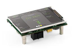
The PCAN MiniDisplay is used as a human-machine interface for the visualization of CAN data. For connection to CAN buses, it has a high-speed and a single-wire CAN connection. The graphical representation of incoming CAN data is configured before the device is used and is then carried out via a TFT display. The PCAN MiniDisplay can also be used as a data logger. In this case, the message traffic is recorded on a memory card and can be evaluated on a PC.
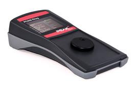
PCAN-Diag 2 is a handheld diagnostic device with versatile functions for examining a CAN bus, such as the determination of the CAN transmission rate, the bus load measurement or the termination measurement. In addition to receiving CAN messages, individual and complete message sequences can be sent. In addition, the internal memory card allows the recording and playback of the message traffic. The integrated 2-channel oscilloscope enables the representation of the CAN signals, whereby individual CAN-IDs as well as different events can be used as triggers. The CAN frames are decoded based on the analogously recorded course, to detect, for example, errors in the frame.
Routers & Gateways
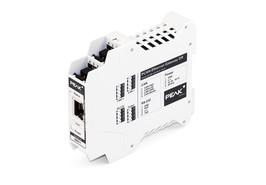
The PCAN Ethernet Gateway DR allows the connection of different CAN buses over IP networks. For this purpose, CAN frames are packaged in TCP or UDP message packets and forwarded from one device to another via the IP network. The PCAN Ethernet Gateway DR provides a LAN port and two high-speed CAN interfaces for this purpose. With the H-rail housing and the support of the extended temperature range, the module is suitable for use in industrial environments. The device is configured via a comfortable web interface. In addition to various status information, settings for the device itself, for the individual communication interfaces and for message transfer are available here.
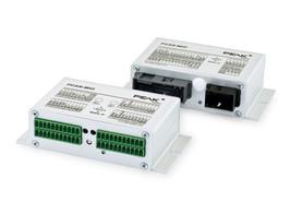
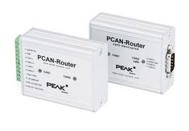
The PCAN router is a two-channel CAN module which offers the possibility to use the CAN messages of both channels flexibly through the freely programmable microcontroller of the NXP LPC21 series. This provides a wide range of possibilities for manipulating, evaluating, filtering and routing CAN messages. Using the supplied library and the GNU-ARM-Toolchain Yagarto (contains the GNU Compiler Collection GCC for C and C ++), a separate firmware can be created and then transferred to the module via CAN. When delivered, the PCAN router is equipped with a demo firmware, which carries out a 1: 1 forwarding of the CAN messages between the two channels at 500 kbit / s. The corresponding source code is included as an example. The module is housed in an aluminum profile housing and is delivered in variants with two D-sub connectors or a screw terminal block.
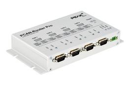
With the PCAN router Pro, the data traffic of four high-speed CAN buses can be linked to one another as desired. The behavior of the router is configured using the included Windows program PPCAN editor via the CAN bus. In addition to the pure forwarding, CAN data can be processed, manipulated and, for example, filtered. For the creation of a configuration, the user has a large number of function blocks and other settings available. In addition, a virtual fifth CAN channel allows the recording of all data traffic on a CompactFlash card. As an alternative to the standard firmware, which is provided with the PCAN router Pro at the time of delivery, it is possible to create and use its own firmware based on the ARM microcontroller NXP LPC2294. Included in the package are a library and the GNU-ARM-Toolchain Yagarto (contains the GNU Compiler Collection GCC for C and C ++).
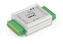
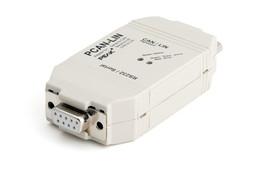
PCAN-LIN enables communication between CAN, LIN and serial devices. The various modes can be set via a configuration software. For example, the module can request data as a LIN master and send the received LIN data to the CAN bus and / or the serial interface. Data can be passed between CAN and LIN with ID offset.
Development Packages
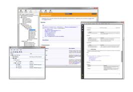
PCAN is a flexible system for the planning, development and use of CAN networks. The basis for the communication of PCs to external hardware via a CAN bus are Windows® kernel mode drivers. These form the core of a complete CAN network environment on a PC running Windows®. This device driver manages the entire data traffic of all hardware connected to the PC. The interface to the user or the operator of a CAN-networked system are so-called PCAN clients. Process variables can be visualized and influenced with their help. The driver allows the connection of several clients, which can communicate with CAN buses. It supports several hardware components, which are based on the CAN controller SJA1000 from NXP. PCAN-Developer consists of a single-user user license for the development package as well as a distribution license for the PCAN-Developer Redistributable. This package contains the API DLLs as well as the software PCAN-View, PCAN-CPL, PCAN-Nets Configuration and PCAN status display.
The Recommended Practice 1210 was defined by the Technology and Maintenance Council (TMC) as a standardized API for communication between Windows® applications and vehicle communications networks. PCAN-RP1210 API of PEAK system is an implementation of RP1210 versions A and C with support for CAN and SAE J1939 networks. This allows the API to develop its own RP1210 applications as well as the use of existing RP1210 applications with CAN adapters from PEAK system. With the PCAN-RP1210 API, you receive a single user license for the development package as well as for the RP1210 connection to PEAK-CAN interfaces. The PCAN-Developer RP1210-Extension also includes a distribution license for the PCAN-RP1210 API-DLLs.
PC Software
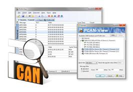
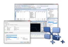
The PCAN-View software for Windows® is a simple CAN monitor for viewing, sending and recording the CAN data traffic. The messages can be sent manually and periodically with an adjustable transmission rate of up to 1 Mbit / s. Faults on the bus system and memory overflows of the controlled CAN hardware are displayed. The CAN traffic can be recorded and stored via the trace function. PCAN-View is part of the scope of delivery of every PCAN-PC hardware and enables its quick and easy commissioning. In the connection dialog, all available PEAK-CAN interfaces are listed for this purpose. After selecting the hardware and setting the transmission rate, you can use all functions of the software and access hardware-specific settings and information.
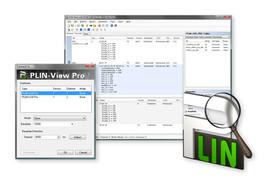
The LIN monitor is included with the PCAN-USB Pro PLIN-View Pro for Windows®. Incoming LIN messages can be viewed through this software, whereby the use of LDF files (LIN Description File) allows the symbolic representation of LIN messages. Outgoing LIN frames can be defined depending on the master or slave operating mode. In addition, the LIN functionality of the PCAN-USB Pro hardware is accessed using PLIN-View Pro, such as the on-board scheduler or the automatic transmission rate detection. The PCAN-USB Pro also includes the PLIN API from PEAK-Systemtechnik. It allows you to develop your own LIN applications for communication with the PCAN-USB Pro.
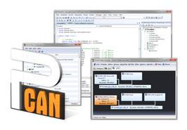
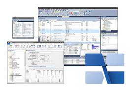
The PCAN-Explorer 6 is a versatile, professional program for working with CAN and CAN-FD networks. The user is not limited to monitoring the CAN traffic. The manual or periodic sending of messages or complete mailing lists allows him direct influence, for example for control purposes or simulations. The PCAN-Explorer 6 can connect at the same time with several CAN and CAN-FD buses. Unlike previous versions, the hardware type of the CAN adapters used is no longer a limiting factor. A crucial point in the use of the program is the symbolic representation of the CAN messages and their user data. The hexadecimal information is converted into a readable and intuitive format with the aid of symbol files.
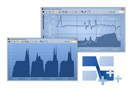
This line recorder allows the recording and graphical display of any number of signal traces. The data of incoming and outgoing CAN messages as well as virtual variables and results of macro calculations can be used as a signal source. Plot Viewer: The free Windows® software Plot Viewer allows you to display the recordings without installing the PCAN Explorer..
The network protocol SAE J1939 describes the communication on a CAN bus in commercial vehicles for the transmission of diagnostic data and control information. It contains a complete network definition using 29-bit CAN-IDs (CAN 2.0B Extended Frame). The add-in J1939 for the PCAN-Explorer 5 supports all the definitions defined by the parameter groups (parameter groups) of the standard and provides easy access to the parameters. A complete data base with all definitions and the included parameters is included.
Adapters
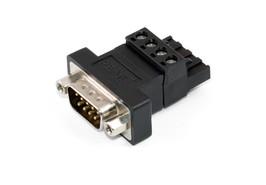
CAN hardware from PEAK system has a 4-pin screw terminal block as CAN connection for versions in the DIN rail housing. The PCAN-D-Sub connector adapts its pin assignment to a 9-pin D-Sub connector. This makes it possible, for example, to connect our standard CAN cables and to connect the device to one of our CAN-PC interfaces. The PCAN-D-Sub connection adapter can be used in CAN-FD buses.
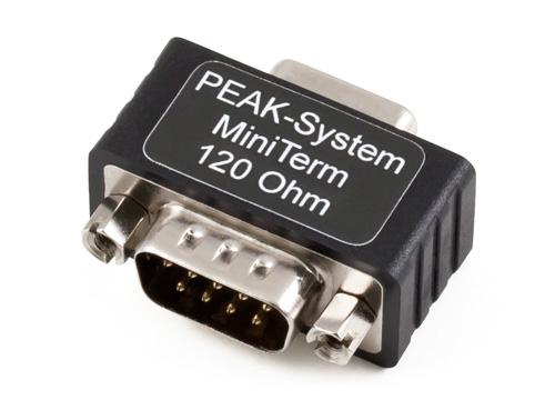
High-speed CAN buses (ISO 11898-2) must be terminated at the ends by a terminating resistor. The PCAN-Term and PCAN-MiniTerm adapters are used when no CAN node or a CAN node without internal termination is connected at these points. The termination adapters can also be used in CAN-FD buses.
The PCAN-T adapter makes a tap of the data lines and the ground within a CAN bus in order to connect a CAN node.The CAN node is not terminated in this case.
Cables
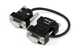
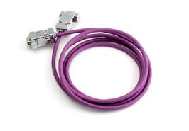
The cables are required to set up a CAN bus and are specially designed for use in a CAN environment. If two high-speed CAN nodes are to be connected directly to one another in a straightforward way, the PCAN cable 2 with integrated termination is suitable. The PCAN cable 1 is suitable for assembling a CAN bus which should contain taps and a separate termination (products PCAN-T adapter and PCAN term). The cables can also be used in CAN-FD buses.
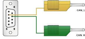
With this cable, the two CAN-High and CAN-Low components of the differential CAN signal can be tapped from a CAN bus or directly from a CAN interface. The banana plugs allow easy connection to test and measurement setups. The PCAN cable 3 can be used in CAN-FD buses.
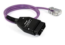
Many modern motor vehicles have the OBD-2 interface for the connection of various diagnostic and test devices. The contained CAN cables can be accessed using this adapter cable
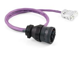
The SAE J1939 protocol specifies uniform CAN messages for communication and diagnosis between heavy-duty vehicles such as construction machines, tractors or agricultural machinery. In this area, robust connectors are often used for the on-board diagnostic connection. The PCAN cable J1939 converts the CAN lines of these connections to a D-Sub socket and thus allows access via PEAK-CAN interfaces.
The network protocol SAE J1939 describes the communication on a CAN bus in commercial vehicles for the transmission of diagnostic data and control information. It contains a complete network definition using 29-bit CAN-IDs (CAN 2.0B Extended Frame). The add-in J1939 for the PCAN-Explorer 5 supports all the definitions defined by the parameter groups (parameter groups) of the standard and provides easy access to the parameters. A complete data base with all definitions and the included parameters is included.