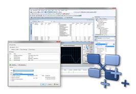
PEAK-System Technik is a leading provider of hardware, software, and services for the industrial communication. The focus is on the field busses CAN and LIN. The product range includes: CAN/LIN interface modules for common PC hardware interfaces (PCI, cPCI, Mini PCI, PCIe, PC/104, USB, PC Card, and ExpressCard), Configurable microcontroller hardware with CAN interfaces for individual developments, measurement data acquisition, and control applications, Various software products for Windows® 7, Vista, and XP, used for diagnosis, monitoring, and influencing of CAN and LIN networks
Accessories
Adapters
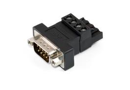
CAN hardware from PEAK system has a 4-pin screw terminal block as CAN connection for versions in the DIN rail housing. The PCAN-D-Sub connector adapts its pin assignment to a 9-pin D-Sub connector. This makes it possible, for example, to connect our standard CAN cables and to connect the device to one of our CAN-PC interfaces. The PCAN-D-Sub connection adapter can be used in CAN-FD buses.
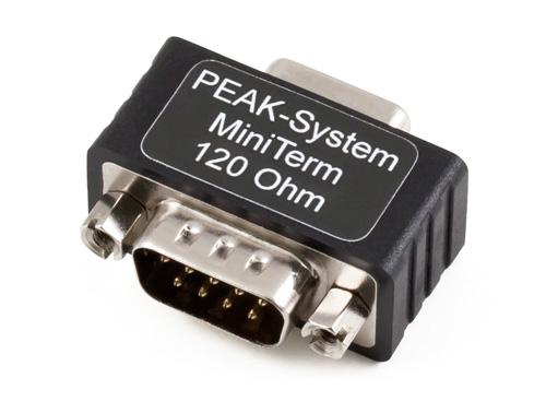
High-speed CAN buses (ISO 11898-2) must be terminated at the ends by a terminating resistor. The PCAN-Term and PCAN-MiniTerm adapters are used when no CAN node or a CAN node without internal termination is connected at these points. The termination adapters can also be used in CAN-FD buses.
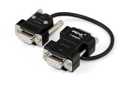
The PCAN-T adapter makes a tap of the data lines and the ground within a CAN bus in order to connect a CAN node.The CAN node is not terminated in this case.
Cables
The cables are required to set up a CAN bus and are specially designed for use in a CAN environment. If two high-speed CAN nodes are to be connected directly to one another in a straightforward way, the PCAN cable 2 with integrated termination is suitable. The PCAN cable 1 is suitable for assembling a CAN bus which should contain taps and a separate termination (products PCAN-T adapter and PCAN term). The cables can also be used in CAN-FD buses.
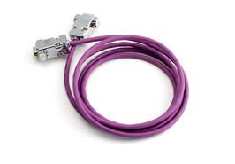
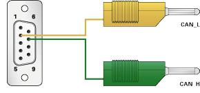
With this cable, the two CAN-High and CAN-Low components of the differential CAN signal can be tapped from a CAN bus or directly from a CAN interface. The banana plugs allow easy connection to test and measurement setups. The PCAN cable 3 can be used in CAN-FD buses.
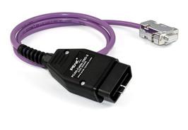
Many modern motor vehicles have the OBD-2 interface for the connection of various diagnostic and test devices. The contained CAN cables can be accessed using this adapter cable
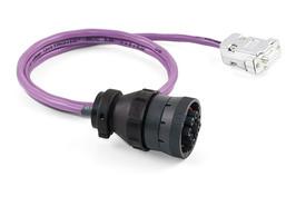
The SAE J1939 protocol specifies uniform CAN messages for communication and diagnosis between heavy-duty vehicles such as construction machines, tractors or agricultural machinery. In this area, robust connectors are often used for the on-board diagnostic connection. The PCAN cable J1939 converts the CAN lines of these connections to a D-Sub socket and thus allows access via PEAK-CAN interfaces.
The network protocol SAE J1939 describes the communication on a CAN bus in commercial vehicles for the transmission of diagnostic data and control information. It contains a complete network definition using 29-bit CAN-IDs (CAN 2.0B Extended Frame). The add-in J1939 for the PCAN-Explorer 5 supports all the definitions defined by the parameter groups (parameter groups) of the standard and provides easy access to the parameters. A complete data base with all definitions and the included parameters is included.
